
Building a laser stabilization system used to mean securing a bulky, expensive analog lock-in amplifier. While effective, these systems can be limited in flexibility, latency, and integration compared to modern digital approaches. Digital devices leveraging digital signal processing outperform their predecessors, which real-world case studies have shown. Is laser stabilization’s future digital?
Laser stabilization is essential. In many laser stabilization setups, the signal representing frequency deviation is extremely weak and often buried in background noise. Environmental disturbances and detector noise can easily dominate the measurement, making reliable extraction of the error signal challenging.
Despite appearances, lasers do not produce perfectly pure color and constant power. Since they are sensitive to their environment, tiny shifts in temperature, vibration, pressure, or power supply can cause the laser’s frequency to drift and power to fluctuate. Even minor changes have significant ramifications in laboratory and educational settings.
For high-precision applications, such as high-resolution spectroscopy, this instability is unacceptable. Individuals must use laser stabilization systems to actively correct fluctuations and lock the laser’s output to a highly stable external reference.
The general method for stabilizing a laser is a feedback loop. A sample of light is split off and sent to a stable reference, and a detector measures the laser’s frequency compared to the stable reference. An error signal of zero indicates that the laser is locked to the reference condition, while deviations above or below zero indicate frequency drift.
Error signals are often incredibly faint because they get buried within background noise. The traditional way to extract it is with an analog lock-in amplifier—a physical box specifically tuned to look for a signal at a specified frequency.
Issues with analog lock-in amplifiers
In the past, creating a laser stabilization system meant buying a stand-alone analog lock-in amplifier that must be physically wired to detectors and other electronic modules. It was effective but inflexible. Professionals had to modify or replace hardware to change the modulation frequency.
Analog lock-in amplifiers have been foundational for sensitive measurements for decades, because they can extract faint signals from extremely noisy environments, where accurate data retrieval is imperative. They effectively served their purpose, but are straining to meet evolving performance expectations. Users can’t easily change the device’s core functions and settings—including operating frequency range, filter types, and time constants.
Digital lock-in amplifiers digitize input signals via digital signal processing algorithms for precise filtering and multifrequency demodulation—without component drift. They are designed for high-performance, real-time, parallel mathematical operations.
Digital implementation replicates the entire function of the analog lock-in box in code on a digital device. It filters and processes numbers to extract the error signal in real time, and a digital-to-analog converter then creates the voltage needed to correct the laser. This approach can surpass analog implementations in performance and functionality, particularly in applications requiring flexibility and integration.
Fundamentals of digital signal processing
The modern approach is to digitize the lock-in amplifier’s core functions. A high-speed analog-to-digital converter (ADC) converts the noisy analog signal from the detector into a stream of digital data. Digital signal processing performs mathematical operations on this information. The output is filtered and processed to extract the error signal in real time.
Turning signals into data. The ADC converts a continuous analog input signal into a discrete series of numbers. Sampling the input voltage at a high, fixed rate produces a data stream that approximates the original waveform. The objective is to compare the input signal to a reference, typically a sine wave.
To do this, the system splits the input signal. Both are multiplied separately with the reference and a 90-degree phase-shifted copy. Unlike analog instruments, digital technology eliminates signal-to-noise ratio losses when splitting the signal. These signals then pass through identical digital low-pass filters for noise removal and data averaging.
The output of the demodulation process is two stable direct current values. To clean them, you use digital filters like the cascaded integrator comb (CIC) or finite impulse response (FIR), which should suppress high-frequency signals and yield a direct current (DC) signal free of noise.
Cleaning signals. CIC is popular because it requires no filter coefficient storage or multiplications. It relies on the simplest of computations—you only need subtraction and addition to implement these filters. You can also achieve low-pass filtering with significantly lower computational complexity than with a FIR.
While FIR still has uses, it requires an extremely low cut-off frequency, which results in complex operations, considerable resource consumption, and higher latency. If you prefer FIR, you can optimize with dual filters that share one coefficient table. This method delivers superior performance, low computational complexity, and low resource utilization.
Minimal delays. After mixing, the signal may still be noisy. To clean it up, the lock-in must average the signal. Averaging is a common source of delays because, by nature, it can’t change instantly and must be measured over time.
If you average a very short time interval, the output will respond very quickly to changes, but you will not filter out much noise. In contrast, averaging over a long period will effectively eliminate noise and yield a clean and stable result, but it will take a long time to respond when the real signal changes.
Set the time constant—which measures how fast a system responds to input—to a very short value. While your output may be noisy, it will respond nearly instantly to any changes. As you gradually increase the time constant, the output will begin to lag. To get the shortest possible averaging time, stop once the signal is stable enough for reliable measurement.
Benefits of digital implementation
With digital lock-in amplifiers, laboratory professionals can change parameters—such as filter settings, modulation frequency, and gain—by simply editing a line of code. There is no need to touch any hardware. Digital control enables more complex, adaptive stabilization techniques that are difficult or impossible to implement with analog components.
Beyond being more intuitive, this system is typically more affordable. A single programmable device will be considerably cheaper than multiple specialized electronic boxes with analog components. In real-world settings, laser stabilization systems with digital signal processing are efficient, powerful, and cost-effective.
Scanning probe microscopy (SPM), for example, provides micro- and nanoscale surface topology maps. Usually, the scanning point layout is defined within rectangular topography raster patterns. The risk of this strategy is that valuable data may be missed due to insufficient scanning density. Also, the system may be overwhelmed by data when a lower resolution would suffice.
A controller that supports adaptive scanning makes data acquisition more efficient. One case study demonstrated that even a low-cost digital signal processor can achieve comparable performance to state-of-the-art commercial microscopes to enable 16-, 18-, and 20-bit operation. This experiment demonstrated the potential of using flexible, off-the-shelf components to create powerful instruments.
A higher bit depth means the controller can measure much smaller height differences. Imaging at the nanoscale requires extreme precision to detect tiny features, and a custom system used add-on boards to increase the native 14-bit resolution to 18- and 20-bit for finer control and measurement.
Laser stabilization system prototypes
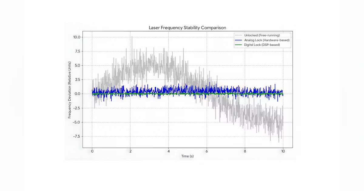
Digital lock-in amplifiers are significantly more accurate than their analog counterparts due to frequency synthesis and phase-sensitive detection (see Fig. 1). Digital implementations offer greater flexibility and scalability, despite added implementation complexity. When designing analog devices, some errors are difficult to mitigate due to the limitations of analog electronics.
Whether quantum optics researchers use digital signal processing to create complex feedback networks or university laboratories teach students the principles of laser physics, these laser stabilization systems are clearly superior to their analog counterparts.
To build an effective system, individuals should move away from messy, outdated hardware toward smart, flexible software. When prototyping, they must set the filter’s time constant as short as possible to balance reaction time and error signal stability. The stabilization feedback loop must be faster than the laser’s drift.
A good lock-in measurement is based on an optimal reference signal. When using an external reference, they must ensure the frequency is well defined and free of phase noise. After conducting some quality assurance measures up front, their system will handle much of the legwork. If adjustments are needed, it is as easy as changing a line of code.