
Microelectrode arrays (MEAs) have diverse applications across a wide range of industries—including microelectromechanical systems (MEMS) for compact precision sensors, test devices for semiconductor chips, and energy storage solutions such as battery or fuel cell technologies. Notably, MEAs also play a crucial role in various medical applications, such as implantable sensors for cardiac electrophysiology, microneedles for drug delivery and skin sensing, and brain-computer interfaces (BCIs).
MEA is a niche market, but demand is poised for significant growth. The total addressable market for BCIs alone is expected to reach $400B by 2045 within the U.S. This rapidly expanding market and numerous other emerging applications underscore the potential for micrometer-sized, high aspect ratio features—as long as current manufacturing challenges can be addressed to push the technology forward.
Automating MEA production is essential to achieve the precision, consistency, and feature sizes these advanced devices require. Current manufacturing methods are primarily reliant on lithography processes, which offer adequate accuracy, but are often time-consuming and costly. Lithographic techniques also frequently impose design constraints because they depend on secondary dicing operations or bulk machining operations, which limits the flexibility of device design and can impact performance.
Addressing these manufacturing limitations is the key to unlock MEAs’ full potential. Emerging approaches such as advanced laser micromachining and automated assembly techniques show promise to improve production efficiency and enhance design versatility. As these methods evolve, the ability to scale MEA production while maintaining precision will help drive broader adoption across medical, electronics, and energy storage sectors.
Microelectrode array manufacturing challenges
Manufacturing MEAs presents several distinct challenges. Implantable BCIs, for example, require biocompatible materials for appropriate electrical performance, which limits the pool of suitable materials to exotic substrates. These electrodes also require extremely small effective diameters with very fine, tapered tips to minimize tissue damage during insertion, but must also be large enough to maintain mechanical integrity. To achieve this balance, electrodes typically must be hundreds of microns long with high aspect ratios to reach targeted brain regions.
Ensuring the quality and consistency necessary for implantable medical devices further complicates production. Device original equipment manufacturers (OEMs) often rely on complex microfabrication techniques such as photolithography or electron-beam lithography to precisely grow the array from silicon-based needles.
These processes typically involve multiple steps—dicing, etching, metallization, deposition, insulation, and deinsulation—to achieve the desired electrode structure and characteristics. Even without the extra steps to ensure performance and reliability, this simplified overview underscores manufacturing’s complexity.
Despite their precision, these microfabrication techniques impose limitations. Electrode length is restricted by practical constraints in bulk machining and dicing processes. As feature sizes shrink, the mechanical stresses introduced during dicing increases and creates the potential for quality issues (especially for high aspect ratio features).
These operations also require cuts at a consistent depth across the width of the part. Subsequent grinding operations can achieve slanted or convoluted profiles, but must be done in a planar or symmetrical fashion across the part surface. But this leads to additional etching steps to generate tipping to the electrodes, which increases manufacturing steps and complexity. Alternative probe or electrode technologies may address these limitations but often come at the expense of channel count, resolution, or cost.
Microelectrode array laser processing
Advanced laser micromachining technology offers a promising solution that significantly reduces production time or steps, increases efficiency, and ultimately lowers costs—while enabling each electrode to have its own unique geometry. Combining modern motion controls, precision stages, and five-axis precession laser scanners provides new capabilities to device designers and manufacturing engineers tasked with scaling device production.
Historically, laser processing applications demanded a complex combination of expertise. It required an understanding of precision motion control to present the substrate to a laser processing head. And the laser scanner often had to be programmed in a separate environment to execute laser scanning of the material, typically with software controls to trigger the laser that were managed separately.
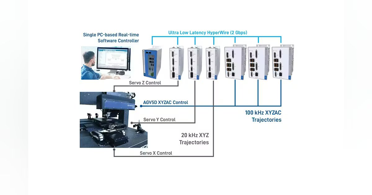
A truly unified control architecture that simultaneously supports the laser and motion-control commands for the precession scanner and linear servo axes benefits the end user in many ways. When all laser scan head and motion axis commands are developed and issued from a common environment, the end user can focus on refining the process instead of troubleshooting disparate control systems and their communications. The integration of this environment also opens up new control possibilities (see Fig. 1).
Since these commands are issued from a common controller, many stitching errors are completely avoided and part quality is improved. It enables throughput enhancements because typical step and scan processes can be simultaneously performed through the laser scan head and motion systems’ continuous motion.
Some motion controllers allow for direct integration of third-party devices. Users can quickly move through development when they directly control the laser source in a single environment—no need to waste time logging out of one interface and into another. If this programming environment allows for native G-Code and M-Code commands to be issued, users who are familiar with typical machine tool programming can quickly adapt common machining approaches through the control software. Ideally, CAD/CAM packages that output either of these formats can be leveraged to produce motion commands to use natively within the control environment. An integrated environment like this allows users to quickly develop and iterate without having to manage each component device used in a laser processing system.
Example microelectrode array
The production process for these types of MEAs is fairly straightforward, given the prevalence of related manufacturing tools. For example, consider the process for creating Figure 2’s sample array. This model is imported to a CAD/CAM package where two machining approaches may be used—free-space beam control and milling.